Main Products

CONTACT US
Address: No.5 Shunhai Road, Yangting Town, Weihai City, Shandong Province
QGBM 'Mi' Type Cylinder
零售价
市场价
Keywords:
QGBM
Category:
Tel:

E-mail:
重量
库存
隐藏域元素占位
- Detail
- Dimension in Inches
-
- Commodity name: QGBM 'Mi' Type Cylinder
- Commodity ID: 224
QGBM series cylinder are new products from international advanced technology. The bore of the cylinder adopted the aluminum alloy which style is like '', without pulling rod. Its appearance are beautiful, they are single piston rod and double action both ends cushioncan adjustable, sealing rings select from Park Company, due to float cushion,so capability are good, outward appearance and dimensions suit to ISO 6431 international standard. This cylinder can replace DNU series of Festo. The cylinder can be installed solenoid.
1. Parameter
Bore(¢) 32 40 50 63 80 100 Max.stroke(mm) 2000 Presuure(MPa) 0.05--0.8 Pressure endurance(MPa) 1.2 Temperature range ºC -20--80 Medium air,dry air Lubrication not required 9or required Thread class GB197-81 6g.6H Thread code G1/8 G1/4 G1/4 G3/8 G3/8 G1/2 Cushion two ends cushion Stroke(mm) S<=500 +2.0
0
+2.5
0
S>=501 +2.5
0
+3
0
Stroke with cushion(mm) 19 21 23 23 30 30 Out power(N) (0.6MPa) push 482 753 1178 1870 3015 4712 pull 415 633 990 1680 2720 4418 2. Weight
Bore(¢) 32 40 50 63 80 100 Weight(Kg) 0.483 0.727 1.146 1.674 2.662 3.864 Kg/10mm stroke(kg) 0.026 0.036 0.048 0.057 0.076 0.09 Weight of mounting parts (Kg) Axis foot 0.225 0.27 0.4 0.48 1.08 1.25 Flange 0.245 0.29 0.52 0.69 1.66 2.395 Moveable trunnion 0.19 0.33 0.535 0.8 1.38 2.745 Double clevis 0.19 0.27 0.445 0.675 1.265 1.79 Single clevis 0.195 0.255 0.43 0.565 0.94 1.51 3. Model Indication

4. Mounting Style
No-sign standard typ S2-parallet to axis foot type MF1-rod side flange type MF2-head side flange type MP4-single clevis type MP2-double clevis type MT4-intermediate movable trunnion type MT1-front movable trunnion type MT2-back movable trunnion type -
1. Standard
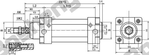
4. MF1 - rod side flange type
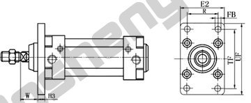
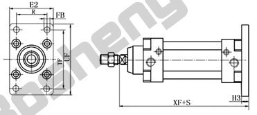
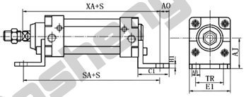
Bore ¢ 32 40 50 63 80 100 AB ¢ 7 10 10 10 12 14.5 AJ 32 36 45 50 63 71 AO 11 12 13 13 19 19 C1 35 40 45 45 60 60 E 45 54 65 80 96 126 E1 44 53 63 73 95 115 E2 45 55 65 75 96 126 FB 7 9 9 9 12 14 H1 5 5 5 5 6 6 H3 10 10 12 12 16 16 J5 18 20 20 26 26 32 J6 16 20 24 24 28 38 L10 18 20 25 28 34 34 L11 136 145 155 167 186 206 LB 73 82.5 60 97.5 110 120 R 32 36 45 50 63 75 SA 142 161 170 179 206 216 TD ¢ 12 16 16 20 20 25 TF 64 72 90 100 126 150 TL 12 16 16 20 20 25 TM 50 63 75 90 110 132 TR 32 36 45 50 63 75 UF 80 90 110 123 154 186 UW 65 75 86 105 120 140 W 16 20 25 28 32 37 XA 144 163 175 187 213 228 XF 130 145 155 167 188 203 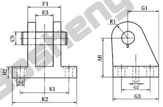
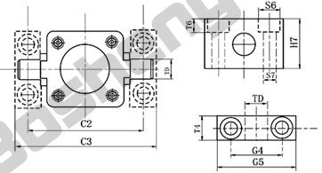
Bore ¢ 32 40 50 63 80 100 Weight kg 0.25 0.35 0.6 0.64 1.1 1.4 AH 32 36 45 50 63 71 CN ¢ 10 12 12 16 16 20 E3 26.2 28.2 32.2 40.2 50.2 60.2 F1 40 42 50 60 75 85 G1 16 20 25 25 30 41 G2 20 26 31 31 36 46 G3 36 41.5 47 47 57 67.5 H2 8 10 12 12 14 15 K1 54 56 66 76 95 105 K2 68 70 80 90 114 124 R1 12 15 15 17 18 22 S3 ¢ 4.8 5.8 5.8 7.8 7.8 9.8 S4 ¢ 6.6 6.6 9 9 11 11 12. MP2 -double clevis type bore-MP2
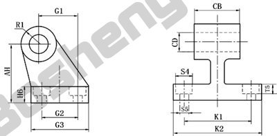
Bore¢ 32 40 50 63 80 100 Weight kg 0.17 0.22 0.38 0.505 0.709 1.25 AH 32 36 45 50 63 71 CB 26 28 32 40 50 60 CD 10 12 12 16 16 20 G1 21 24 33 37 47 55 G2 18 22 30 35 40 50 G3 31 35 45 50 60 70 H6 8 10 12 12 14 15 K1 38 41 50 52 66 76 K2 51 54 65 67 86 96 R1 10 11 11 15 15 19 S4¢ 10 10 11 15 15 15 S5¢ 5.5 5.5 6.6 6.6 9 9 T5 5.7 5.7 6.8 6.8 9 9
QGBM 'Mi' Type Cylinder
QGBM series cylinder are new products from international advanced technology. The bore of the cylinder adopted the aluminum alloy which style is like '', without pulling rod. Its appearance are beautiful, they are single piston rod and double action both ends cushioncan adjustable, sealing rings select from Park Company, due to float cushion,so capability are good, outward appearance and dimensions suit to ISO 6431 international standard. This cylinder can replace DNU series of Festo. The cylinder can be installed solenoid.
keyword:
Category:
Pneumatic Cylinder
Tel:

E-mail:
- Detail
- Dimension in Inches
-
- Commodity name: QGBM 'Mi' Type Cylinder
- Commodity ID: 224
QGBM series cylinder are new products from international advanced technology. The bore of the cylinder adopted the aluminum alloy which style is like '', without pulling rod. Its appearance are beautiful, they are single piston rod and double action both ends cushioncan adjustable, sealing rings select from Park Company, due to float cushion,so capability are good, outward appearance and dimensions suit to ISO 6431 international standard. This cylinder can replace DNU series of Festo. The cylinder can be installed solenoid.
1. Parameter
Bore(¢) 32 40 50 63 80 100 Max.stroke(mm) 2000 Presuure(MPa) 0.05--0.8 Pressure endurance(MPa) 1.2 Temperature range ºC -20--80 Medium air,dry air Lubrication not required 9or required Thread class GB197-81 6g.6H Thread code G1/8 G1/4 G1/4 G3/8 G3/8 G1/2 Cushion two ends cushion Stroke(mm) S<=500 +2.0
0
+2.5
0
S>=501 +2.5
0
+3
0
Stroke with cushion(mm) 19 21 23 23 30 30 Out power(N) (0.6MPa) push 482 753 1178 1870 3015 4712 pull 415 633 990 1680 2720 4418 2. Weight
Bore(¢) 32 40 50 63 80 100 Weight(Kg) 0.483 0.727 1.146 1.674 2.662 3.864 Kg/10mm stroke(kg) 0.026 0.036 0.048 0.057 0.076 0.09 Weight of mounting parts (Kg) Axis foot 0.225 0.27 0.4 0.48 1.08 1.25 Flange 0.245 0.29 0.52 0.69 1.66 2.395 Moveable trunnion 0.19 0.33 0.535 0.8 1.38 2.745 Double clevis 0.19 0.27 0.445 0.675 1.265 1.79 Single clevis 0.195 0.255 0.43 0.565 0.94 1.51 3. Model Indication

4. Mounting Style
No-sign standard typ S2-parallet to axis foot type MF1-rod side flange type MF2-head side flange type MP4-single clevis type MP2-double clevis type MT4-intermediate movable trunnion type MT1-front movable trunnion type MT2-back movable trunnion type -
1. Standard

4. MF1 - rod side flange type
Bore ¢ 32 40 50 63 80 100 AB ¢ 7 10 10 10 12 14.5 AJ 32 36 45 50 63 71 AO 11 12 13 13 19 19 C1 35 40 45 45 60 60 E 45 54 65 80 96 126 E1 44 53 63 73 95 115 E2 45 55 65 75 96 126 FB 7 9 9 9 12 14 H1 5 5 5 5 6 6 H3 10 10 12 12 16 16 J5 18 20 20 26 26 32 J6 16 20 24 24 28 38 L10 18 20 25 28 34 34 L11 136 145 155 167 186 206 LB 73 82.5 60 97.5 110 120 R 32 36 45 50 63 75 SA 142 161 170 179 206 216 TD ¢ 12 16 16 20 20 25 TF 64 72 90 100 126 150 TL 12 16 16 20 20 25 TM 50 63 75 90 110 132 TR 32 36 45 50 63 75 UF 80 90 110 123 154 186 UW 65 75 86 105 120 140 W 16 20 25 28 32 37 XA 144 163 175 187 213 228 XF 130 145 155 167 188 203 
Bore ¢ 32 40 50 63 80 100 Weight kg 0.25 0.35 0.6 0.64 1.1 1.4 AH 32 36 45 50 63 71 CN ¢ 10 12 12 16 16 20 E3 26.2 28.2 32.2 40.2 50.2 60.2 F1 40 42 50 60 75 85 G1 16 20 25 25 30 41 G2 20 26 31 31 36 46 G3 36 41.5 47 47 57 67.5 H2 8 10 12 12 14 15 K1 54 56 66 76 95 105 K2 68 70 80 90 114 124 R1 12 15 15 17 18 22 S3 ¢ 4.8 5.8 5.8 7.8 7.8 9.8 S4 ¢ 6.6 6.6 9 9 11 11 12. MP2 -double clevis type bore-MP2

Bore¢ 32 40 50 63 80 100 Weight kg 0.17 0.22 0.38 0.505 0.709 1.25 AH 32 36 45 50 63 71 CB 26 28 32 40 50 60 CD 10 12 12 16 16 20 G1 21 24 33 37 47 55 G2 18 22 30 35 40 50 G3 31 35 45 50 60 70 H6 8 10 12 12 14 15 K1 38 41 50 52 66 76 K2 51 54 65 67 86 96 R1 10 11 11 15 15 19 S4¢ 10 10 11 15 15 15 S5¢ 5.5 5.5 6.6 6.6 9 9 T5 5.7 5.7 6.8 6.8 9 9
Product Message
Other Products


