Main Products

CONTACT US
Address: No.5 Shunhai Road, Yangting Town, Weihai City, Shandong Province
JB Series Cylinder
零售价
市场价
Keywords:
JB Series
Category:
Tel:

E-mail:
重量
库存
隐藏域元素占位
- Detail
- Dimension in Inches
-
- Commodity name: JB Series Cylinder
- Commodity ID: 227
JB series cylinder are suit to JB1444--1148 standard,usually used for metal equipment,they are heavy cylinder with cushion set, working medium is compress oil air after treating by filter.
1. Parameter
Inner Diameter 80 100 125 160 180 200 250 320 400 Stroke Range (mm) 60-800 60-800 80-2000 80-2500 100-2500 100-2500 125-2500 125-2500 125-2500 Pressure Range (MPa) 0.15-0.8 0.15-0.8 0.1-0.8 0.1-0.8 0.1-0.8 0.1-0.8 0.1-0.8 0.1-0.8 0.1-0.8 Temperature -90 Theoretical Applied Force (N) (at 0.4MPa) Push 2000 3150 4900 8050 10200 12600 19600 32150 50300 Pull 1700 2850 4400 7500 9400 11800 18100 29600 47700 2. Symbol
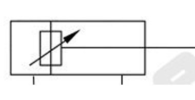
3. Model Indication
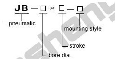
No-standard
S-rod end single clevis type F-rod side flange type
F-head side flange type
G-vertical to axis type
B-intermediate movable trunnion type
-
1. Standard
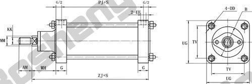
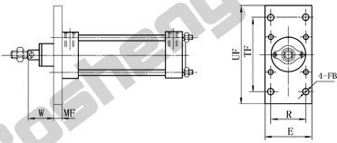
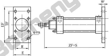
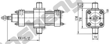
Bore(mm) Ф80 Ф100 Ф125 Ф160 Ф180 Ф200 Ф250 Ф320 Ф400 AM 35 35 40 40 50 50 60 70 70 B Ф95 Ф95 Ф130 Ф130 Ф170 Ф170 Ф200 Ф240 Ф240 DD M12 M12 M16 M16 M20 M20 M24 M30 M30 EE M14*1.5 M14*1.5 M18*1.5 M18*1.5 M18*1.5 M18*1.5 M27*2 M33*2 M33*2 G 30 30 40 40 40 40 60 60 60 KK M20*1.5 M20*1.5 M24*2 M24*2 M30*2 M30*2 M42*3 M56*4 M56*4 MM Ф30 Ф30 Ф40 Ф40 Ф50 Ф50 Ф70 Ф70 Ф70 PJ 105 105 140 140 150 150 180 200 200 TV 85 100 120 150 170 190 230 280 350 UG 115 130 160 190 220 240 290 350 430 WH 70 70 90 90 110 110 150 190 190 ZJ 205 205 270 270 300 300 390 450 450 Bore Ф 80 100 125 160 180 200 250 320 400 AB Ф 13 13 17 17 21 26 26 33 33 AH 85 95 115 130 150 160 195 250 285 AO 28.5 28.5 29.5 40 56 56 56.5 85 85 AT 8 8 10 10 14 14 16 20 20 CD Ф 25 25 30 30 35 35 40 50 50 E 30 30 40 40 50 50 60 80 80 EW 30 30 40 40 50 50 60 80 80 FB Ф 13 13 17 17 21 21 26 33 33 L 30 30 40 40 50 50 60 70 70 MF 16 16 20 20 25 25 30 40 40 MR 25 25 30 30 35 35 40 50 50 R 85 100 120 150 170 190 230 280 350 SA 226 226 280 280 328 328 447 490 490 TD Ф 30 30 40 40 50 50 70 90 90 TF 145 160 200 230 260 280 340 420 490 TL 30 30 40 40 50 50 70 90 90 TM 150 175 210 240 270 300 360 420 530 TR 145 150 190 210 230 260 320 350 390 UF 180 200 240 270 320 340 410 500 570 UM 210 235 290 320 370 400 500 600 710 W 54 54 70 70 85 85 120 150 150 XA 250.5 250.5 330 330 369 369 493.5 565 565 XD 225 255 330 330 375 375 475 560 560 XV 137.5 137.5 180 180 205 205 270 320 320 ZF 221 221 290 290 325 325 420 490 490
JB Series Cylinder
JB series cylinder are suit to JB1444--1148 standard,usually used for metal equipment,they are heavy cylinder with cushion set, working medium is compress oil air after treating by filter.
keyword:
Category:
Pneumatic Cylinder
Tel:

E-mail:
- Detail
- Dimension in Inches
-
- Commodity name: JB Series Cylinder
- Commodity ID: 227
JB series cylinder are suit to JB1444--1148 standard,usually used for metal equipment,they are heavy cylinder with cushion set, working medium is compress oil air after treating by filter.
1. Parameter
Inner Diameter 80 100 125 160 180 200 250 320 400 Stroke Range (mm) 60-800 60-800 80-2000 80-2500 100-2500 100-2500 125-2500 125-2500 125-2500 Pressure Range (MPa) 0.15-0.8 0.15-0.8 0.1-0.8 0.1-0.8 0.1-0.8 0.1-0.8 0.1-0.8 0.1-0.8 0.1-0.8 Temperature -90 Theoretical Applied Force (N) (at 0.4MPa) Push 2000 3150 4900 8050 10200 12600 19600 32150 50300 Pull 1700 2850 4400 7500 9400 11800 18100 29600 47700 2. Symbol

3. Model Indication

No-standard
S-rod end single clevis type F-rod side flange type
F-head side flange type
G-vertical to axis type
B-intermediate movable trunnion type
-
1. Standard

Bore(mm) Ф80 Ф100 Ф125 Ф160 Ф180 Ф200 Ф250 Ф320 Ф400 AM 35 35 40 40 50 50 60 70 70 B Ф95 Ф95 Ф130 Ф130 Ф170 Ф170 Ф200 Ф240 Ф240 DD M12 M12 M16 M16 M20 M20 M24 M30 M30 EE M14*1.5 M14*1.5 M18*1.5 M18*1.5 M18*1.5 M18*1.5 M27*2 M33*2 M33*2 G 30 30 40 40 40 40 60 60 60 KK M20*1.5 M20*1.5 M24*2 M24*2 M30*2 M30*2 M42*3 M56*4 M56*4 MM Ф30 Ф30 Ф40 Ф40 Ф50 Ф50 Ф70 Ф70 Ф70 PJ 105 105 140 140 150 150 180 200 200 TV 85 100 120 150 170 190 230 280 350 UG 115 130 160 190 220 240 290 350 430 WH 70 70 90 90 110 110 150 190 190 ZJ 205 205 270 270 300 300 390 450 450 Bore Ф 80 100 125 160 180 200 250 320 400 AB Ф 13 13 17 17 21 26 26 33 33 AH 85 95 115 130 150 160 195 250 285 AO 28.5 28.5 29.5 40 56 56 56.5 85 85 AT 8 8 10 10 14 14 16 20 20 CD Ф 25 25 30 30 35 35 40 50 50 E 30 30 40 40 50 50 60 80 80 EW 30 30 40 40 50 50 60 80 80 FB Ф 13 13 17 17 21 21 26 33 33 L 30 30 40 40 50 50 60 70 70 MF 16 16 20 20 25 25 30 40 40 MR 25 25 30 30 35 35 40 50 50 R 85 100 120 150 170 190 230 280 350 SA 226 226 280 280 328 328 447 490 490 TD Ф 30 30 40 40 50 50 70 90 90 TF 145 160 200 230 260 280 340 420 490 TL 30 30 40 40 50 50 70 90 90 TM 150 175 210 240 270 300 360 420 530 TR 145 150 190 210 230 260 320 350 390 UF 180 200 240 270 320 340 410 500 570 UM 210 235 290 320 370 400 500 600 710 W 54 54 70 70 85 85 120 150 150 XA 250.5 250.5 330 330 369 369 493.5 565 565 XD 225 255 330 330 375 375 475 560 560 XV 137.5 137.5 180 180 205 205 270 320 320 ZF 221 221 290 290 325 325 420 490 490
Product Message
Other Products


